Like all GD&T (Geometric Dimensioning and Tolerancing) – the meaning is directly tied to both how the part would function and how it would be inspected during or after manufacturing. This topic is actually fairly detailed, but I’ll try to stick to the concept – per the question. I’ll try to hold off on the dry definition part of the question until after the concept is explained.
Part I – The Concept
Parts that are radially symmetric (like pins) or that will rotate in operation (shafts, hubs, gears etc.) will never be perfectly straight. The axes of these parts will never be perfect lines – they may be bowed, bent, curved etc. If these types of parts have multiple surfaces (like a shaft with multiple diameters, shoulders, tapers…) these surfaces will never be perfectly concentric. So the question is – how straight do the features of these parts need to be? What is the range of acceptable shapes and relative positions and orientations of these features? The answer to these questions depends on the functions of the part in question and total indicated runout gives us a way to specify these requirements.
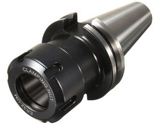
Let’s discuss a few examples. Suppose you are making a tool holder which has a big taper on one end where the holder fits into the spindle of a machine tool. The strength and accuracy of that tool holder depends on the mating tapers in the tool holder and spindle having very good contact over a large conical area. We want to be able to specify that our taper is not only a certain angle – but also that it’s very circular in all cross sections and that the profile of the taper very smooth and straight – not wavy. Total indicated runout helps us specify this. How? See Part II.
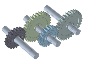
Another case would be a shaft on which a gear is mounted. The shaft will spin about the axis between the two centers of the bearings on which it is mounted. However, if the gear is mounted on a surface in the middle of the shaft that is not in line with the bearings then the gear will bind with its mating gear – or it may run loose with too much backlash and a propensity to wear out. We must be able to ensure the mounting surface for the gear is straight and also parallel and also concentric with the bearing surfaces on the same shaft. The center distances between two gears is critical but the only thing controlling where those centers are is the location of the bearings and the straightness of the shaft on which the gear rides.
Part II – Total Indicated Runout Defined
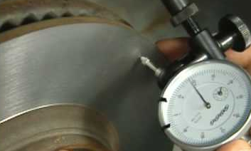
Total indicated runout (which before the days of the double arrow GD&T symbol was specified on drawings by writing “T.I.R.”) is measured by setting up a part so that it rotates about a particular axis, then a dial indicator is used to measure a surface of interest as the part is rotated. The difference between the two most extreme measurements of the indicator from anywhere on that surface is the total indicated runout.
Part III – More GD&T
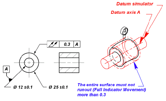
So as the earlier image above indicates – the tolerance you put on a drawing for total indicated runout is the radial width between two theoretically perfect surfaces that are exactly coaxial with the rotation axis you have chosen as a datum for the surface being measured. The two most extreme points read by the indicator must be no further apart than that tolerance value. This is important because these surfaces enclose what is called the tolerance zone and the shape of the part itself determines the shape of that zone. For example, straight shafts would have two concentric cylinders as a tolerance zone and a taper would have two cones enclosing a tolerance zone… For a part to be compliant with the given tolerance requirement, every point on the measured surface must lie within the tolerance zone.
How all of this relates to and contrasts with lots of other GD&T concepts – circularity, concentricity, straightness, profile tolerance, true position etc. is complex but suffice it to say it all depends on how you need the part to function and consequently how you want the extremes of part shape to come out. A part could be perfectly circular in every cross section but have terrible total runout if it’s axis is not straight. So diameter dimensions and even 2D runout or circularity tolerances are often not enough to control a critical part.
See The Video Below.