See also Locking Devices
Machine Screws
Machine screws are generally stronger than wood screws, have finer threads and are made more precisely. They’re used with nuts or tapped holes. Several examples are shown below.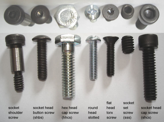
- Socket Screws: While many hex cap screws may be found in vehicles, socket head screws are becoming more popular and have some space saving advantages over hex cap screws. Socket heads take up less space themselves and don’t require side room for wrenches. They also are usually made from stronger alloy steel vs. hex cap screws, but this depends on the grade and manufacturer.
- Allen / Hex Socket vs Torx: Most socket head screws accept a hex or Allen wrench (6 sided), but Torx heads (loosely, a 6 pointed star) are also available. Torx sockets were originally designed to prevent the driver from coming out, and can transfer more torque than a Phillips or slotted driver. They don’t require large amounts of pressure to keep the bit in the socket. Some people say that it’s faster to insert a bit into a Torx screw than a hex socket, which would be advantageous in manufacturing environments.
- Button Head: This head is largely decorative and somewhat similar to a round head, but flatter.
- Flat head (counter sunk): These require a pre-drilled counter sink, and are typically angled at 82 degrees (Unified thread), which, by the way, is not the angle created by most drill bits (118 degrees). Metric flat heads have 90 degree angles.
- Shoulder Screws: These have precision ground shanks that remain above the head of a hole and provide a simple way to make an axle for a wheel. They are also used when something must be secured, but not clamped.
- Set Screws: These are threaded along their entire length and are typically used to secure a shaft from rotating. They’re used in pulleys, sprockets, collars and knobs among other things.
Thread Types: Most common types and when to use which
The most common thread types are the inch-based Unified coarse / fine (UNC/UNF) and metric coarse / fine. Other types and their purposes are described at the end of this section.
Coarse or Fine? To oversimplify, use a coarse thread unless you’re tapping into sheet metal. The differences are:
- Coarse threads have fewer threads per inch than fine threads.
- Coarse threads are more common, and more shops will have coarse taps.
- Coarse threads are less likely to cross-thread, or jam because the screw is inserted at an angle. They’re also faster to install.
- Screws with fine threads are slightly stronger. This is because the smaller fine threads take up less of the available area. See the loading charts below to see typical differences between the tensile strength of a fine vs coarse thread. A 1/4 UNF thread is about 14% stronger than its UNC counterpart.
- Coarse threads are slightly stronger (against stripping) per length of engagement than finer threads (see thread strength section below). This may be surprising given the almost universal recommendation that fine threads be used in sheet metal and other thin-walled materials. If coarse threads are stronger and there is less than optimal thread engagement length available, wouldn’t it better to use the stronger threads?
- Coarse threads are more tolerant to slight damage or corrosion than fine threads since they have more room for error.
- Fine threads provide finer adjustment since they advance less per rotation than coarse threads.
- The metric coarse thread is actually between UN coarse and fine thread, and the metric fine thread is finer than the UNF threads. Blake’s “What Every Engineer Should Know About Threaded Fasteners: Materials and Design,” recommends not using fine metric threads.
Thread specification – How threads are notated / designated:
example Unified thread designation:
1/4-20 UNC-2A
- 1/4 – the nominal diameter, also the major / largest diameter
- -20 – the number of threads per inch
- UNC – UNC = Unified Coarse, UNF = Unified Fine. You may also see UNRC or UNRF. These refer to an external Unified Rounded thread (there is no internal rounded thread). UNRC’s and UNRF’s are interchangeable with their non-R counterparts. The only difference is that the valleys (roots) of external R threads have a mandatory rounded shape, whereas with the UNC and UNF threads the roundness is optional.
- -2A – This represents the tolerance / fit of the thread. There are 6 common options, 1A, 2A, 3A, 1B, 2B, and 3B. A=external, B=internal. 1 is the loosest fit, 3 is the most precise and tightest fit with potentially zero clearance. If the tolerance isn’t specified, chances are it’s the more common 2A or 2B designation. 1 is hardly used, and only in cases where frequent re-assembly is needed or the threads need to work even with significant damage. Class 3 have slightly greater stripping resistance, and are common in the aerospace industry.
example ISO Metric thread designation:
M6 x 1 -4g6g or M6-6g
- M6- M is for metric, 6 is the major diameter and nominal size in mm
- x 1 – Pitch. Note that this is different from how Unified threads are specified. UN threads write the number of threads per inch after the nominal size, whereas metric designations write 1 / threads_per_inch after the nominal size. If this is absent, coarse pitch is assumed.
- -4g6g – This is the tolerance / fit class. The number refers to a manufacturing tolerance window, higher numbers are “sloppier.” The letter places that tolerance window relative to the ideal thread. Capital letters refer to internal threads, lowercase external. An h/H has the least amount of allowance-ie, there could be no clearance. g/G and lower represent more allowance. The two Number Letter pairs apply to pitch grade/tolerance and major diameter grade/tolerance for external threads, pitch and minor diameter for internal threads. When only one pair is present (as in M6-6g) it applies to both pitch and major/minor dia. 6g/6H is approximately equivalent to 2A/2B, 4h6h/4H5H is approximately equivalent to 3A/3B, although 4g6g/6H is usually used, which provides a little clearance over 3A/3B.
* a -LH at the end of either inch or metric threads indicates Left Handed threading.
* a (22) or other number at the end refers to the ANSI series of threads.
Some history and info about other threads:
In 1949, Canada, the United Kingdom, and the US agreed to a Unified thread that is largely the same as the American National thread that came before it, and screws from both systems are interchangeable. The new Unified system bascially added more manufacturing tolerances and tweaked some other ones. See ANSI/ASME B1.1 -1989 (R2001) for details.
Metric threads are specified in ANSI B1.13M-1982 (R1995), which is very nearly equivalent to the original ISO 68 specification.
Camera mount threads: These are generally a coarser old standard called the “Whitworth” 1/4 inch diameter and 20 threads per inch.
UNJ or MJ: These threads are used in situations where fasteners must withstand high fatigue stress, predominantly the aerospace industry. The basic difference between UNJ and UN is a larger root radius. Avoidance of sharp corners is critical for fatigue resistance. The root is given a large enough radius that it could potentially interfere with a typical UN internal thread, so there are both external and internal UNJ threads (and MJ’s). According to Blake, it is statistically highly likely that an external UNJ thread will fit a regular internal UN thread.
Standards: In general, the geometry is defined by ANSI, ASME and the ISO, while material strength properties are defined by ASTM, IFI, SAE and ISO.
Cut vs. Rolled Threads: This refers to how threads are manufactured. Rolled threads are stronger than cut/ground threads because they are strain hardened when they are made, and the internal grains of the metal are not cut. The Unified standard doesn’t demand that the roots (valleys) of external threads be rounded, but just about all fasteners less than 1″ come that way because their threads are rolled (see Blake book ref. above), and rolling produces rounded roots.
Constant pitch series: This refers to the many series of threads where the pitch does not increase with diameter. The 8-UN (8 threads / inch) series is apparently very popular above 1″ diameter fasteners. Typically these are used for adjustment devices and not fasteners.
Extra fine threads and miniature screws: The Machinery’s Handbook has listings of dimensions for really small screws.
Power Screws and ACME Threads: Power screws’ job is to translate rotational motion into linear motion. Because of this, efficiency is a concern, and the 60 degree thread profile in standard fasteners is unsuited. The most efficient thread would be square with 90 degree angles, but this is difficult to manufacture, so the ACME thread is used (this has a 15.5 degree angle between root floor and tooth wall). Why is square more efficient? None of its force goes into pushing outward, whereas a 60 degree thread has a substantial force component away from the axial direction of the screw.
Sizing and Strength: How big a screw is needed?
At first thought, sizing a screw for a given load would seem to be a simple matter. If you need to hold 100 lbs, find a screw that can hold 100 lbs before it yields…
But things are not so simple. If a screw can withstand 100 lbs of force before yielding, it is recommended for a number of reasons (discussed in the next section) that it be tightened to about 80 lbs of tension / clamping force just for installation alone. Does that mean that it can only withstand another 20 lbs of external load before it yields? Why would we tighten a screw so much if we’re using up the majority of its strength just to hold it in place? It turns out that only a portion of the external load is seen by the bolt, a rough estimate is about 1/3, but this depends on lots of things.
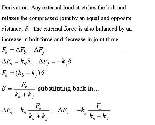
It seems reasonable to think that the tension on a screw / bolt is the sum of the initial clamping load plus any external loads, but this is not so. Consider the following picture and imagine that the screw (or spring) is clamping the red box against the ground with 10 lbs of force. Now, if you were to pull up on the red box with 5 lbs of force, would the tension in the screw increase to 15 lbs? No, your 5 lbs of upwards force would only reduce the pressure between the red box and the ground; it would not stretch the screw at all. In fact, the screw would not feel any change in force whatsoever until the upward force exceeded 10 lbs and the red box lifts. The force / tension in a spring depends only on its stretch (F=kx), and if the bolt head isn’t moving, the tension isn’t changing.

In most situations, however, the ground would act as a spring, too (in compression). As an external load is applied, the ground would decompress as the clamping force lowered, so the bolt head would indeed move slightly. In the end, a screw / bolt feels some fraction of an external load, and the amount it feels depends on how the spring rate of of the bolt compares to the spring rate of the joint (ground in picture). If you know the spring rates of the bolt and joint, the following equations will tell you how much force each feels for a given preload and external load. Here’s another good explanation of this. 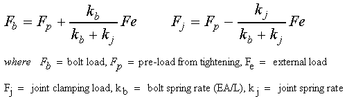
Of course, calculating the joint spring rate is a dubious matter and we encourage you to read Unbrako’s engineering guide if you’re designing anything that remotely matters.
For hobbyists designing things that aren’t mission critical, it’s probably not unreasonable to assume that about 1/3 of the external load is felt by the bolt, but in stiff joints with very flat surfaces (bumpy surfaces add to joint-sponginess), less than 1/7 of the load could be placed on the bolt. Of course, on rubber gaskets, 100% would be felt by the bolt. Another rule of thumb is to make sure the preload is at least twice any external loads to reduce the risk that clamping force will be lost–when this happens bolt loosening is highly likely.
Here’s a rough guide for picking a screw or bolt for a given load:
Start off with the load that needs to be held in tension, call this F. If you have a shear (sideways) load, you should design so that friction or dowel pins will bear the load and not the bolt, but if this isn’t an option note that shear strength is 60% of tensile strength in many steels.
We’ll use a safety factor of 2.5, so the design load is now 2.5F. Now we need to select a screw with enough strength so that it can withstand the combined external load and preload from tightening. Assuming that 80% of the bolt’s proof strength is being used up in preload, that leaves 20% to handle 1/3 of the external load. Or in other words, we’re looking for a bolt where 60% of its proof strength is greater than the load.
Let’s try an example: What size grade 2 bolt is necessary to hold 100 lbs? The proof strength of Grade 2 bolts between .24 and .75 inches is 55 ksi (thousand pounds per square inch), and 60% of this is 34.2 ksi. So, we’re looking for a bolt with a tensile area greater than our load (2.5*100 lbs) divided by 33 ksi, or .0076 square inches. A #6 UNC should work. For perspective the diameter of a #6 screw is .138″, (1/8 = .125″). If this seems small, keep in mind that the ultimate strength (breaking strength) of a Grade 2 bolt is 74 ksi, so a #6 screw could theoretically hold 672 lbs in pure tension. If you’re wondering why bolts you see in cars and weight machines are so large, it’s partly to guard against loosening and fatigue failure in addition to safety factors.
What about changing loads? According sources, over 85% of failures are due to fatigue and not a simple overloading situation. Think about breaking a paper clip, which is easier: bending it back and forth or out-right pulling it apart? If you have an oscillating load and want a joint to last forever, the best advice we can offer is to multiply the anticipated load by 10 or more, and even this may not be sufficient. Steel can handle about half of its ultimate strength in an alternating load, but add in the pre-load stress and something called a “Stress Concentration Factor” due to the threads and the problem gets more complicated quickly. Here’s a good explanation of these effects along with a lot of other great screw information.
Installation: How tight should a screw be? (very)
In the tables below, we use 80% of proof strength as an estimate for the amount of stress on a correctly tightened bolt just due to its installed clamping force, without any external loads. The Machinery’s handbook recommends 50-80% of ultimate tensile strength, or 75-90% of yield or proof strength (75% for reusable joints, 90% for permanent). Some screws are even tightened to yield. It would seem that this level of installation tightness leaves very little strength left over to handle external loads… why do this?
- The tighter the screw, the more friction there is to resist loosening.
- Screws are very likely to come loose if any relative motion occurs between the threads. Static friction is substantially higher than sliding friction, so once movement in one direction starts, it becomes much easier for un-screwing motion to happen, also. A high clamping force creates more friction between the clamped surfaces and therefore reduces the chances they will slide relative to each other.
- As a followup, bolts are less strong against shear (sideways) loads, so more clamping force and friction helps reduce these loads, also.
- Fatigue loading:This is possibly the most common reason sited for extremely high initial tightness. As derived above, as long as the external load doesn’t cause separation in the joint, only a portion of it is actually seen by the bolt. This is especially helpful in cases with alternating loads because the lifespan depends heavily on the magnitude of the changing load, not just its average. In many cases it’s better to have a higher average stress and lower alternating load, and this is the trade off that a high preload supplies.One subtle point is that the percentage of the load seen by the bolt only depends on the relative stiffness of the joint and bolt, not on the amount of preload. As long as joint separation does not occur, additional tightening preload does not buy any additional fatigue protection. Large initial preloads still protect against joint separation, but unless you know otherwise, it’s probably not worthwhile to tighten right up near yield.
- A tighter initial clamping force can actually increases the joint stiffness slightly by flattening somewhat uneven joint surfaces. If only a small pre-load is applied, the joint members might be resting on hills on their surfaces which could get worn down or compressed over time.
How to achieve the required tightness
According to the Machinery’s handbook, tightening by feel is only +-35% accurate, and using a torque wrench only improves the accuracy to about +-25%. These uncertainties are massive, and give good reason not to tighten too close to yield, or too loose, and also to design a joint so that it will still work with a huge span of possible pre-loads. A method called “turn-of-nut” can supposedly get within +-10%, but this relies heavily on a reliable starting point from which to start counting turns (see Machinery’s handbook).
If the application is critical (and you are not relying on this guide), ultrasonic sensing of the bolt length or drilling a hole down the middle and attaching strain gauges will achieve much higher accuracy. Friends in the navy have told us that workers will sometimes heat a very large bolt during installation to utilise its cooling stretch in achieving proper preload.
To add two more variables, additional torsional loads are present during installation, although these usually dissipate shortly afterwords. It can also be assumed that, due to a variety of factors (surface smoothness, uneven loads, thread deformation), some 10% of preload will be lost.
Why is a torque wrench so imprecise? Friction. Some 80+% of applied torque goes into defeating friction, leaving little for actually stretching the bolt. What’s worse is that this friction is highly unpredictable and depends heavily on the materials involved and any lubrication that may be present. Most fasteners have a small amount of oil present from the manufacturer to prevent rust.
From the machinery’s handbook, the following equation can be used to approximate the required torque for a given preload:
Torque = K x preload x nominal_diameter
where K is a friction constant that depends on material and lubrication
| material | K |
|---|---|
| mild-steel, 1/4 – 1 inch dia. | .2 |
| nonplated black finish | .3 |
| zinc-plated | .2 |
| lubricated | .18 |
| cadmium-plated | .16 |
Just to get a flavor, using K=.2 and 80% of 120 ksi proof strength for a SAE Grade 8 1/4 bolt, the above formula gives a seating torque of about 150 in-lbs, or about 13 lbs at the end of a foot long wrench.
Another method recommended by the Machinery’s Handbook is to measure the torque necessary to break a test bolt, and then use 50-60% of this value. This will supposedly be 60-70% of yield.
Many sources offers a charts with recommended torques for various grades and sizes of screws.
Grade and Strength Information
There are numerous standards that fasteners are manufactured to, and those standards describe everything from material chemistry to surface finish to heat treatment. The most relevant numbers are “Proof Stress,” “Yield Stress” and “Tensile / Ultimate Stress.” Tensile Strength is how much stress the material can withstand before finally ripping apart. Yield Stress is the amount of stress that a material can undergo before permanently stretching. Proof stress is similar to Yield stress except that it is slightly less (about 90%), and only applies to fasteners. The thread geometry causes them to yield slightly before the Yield stress level of the material, so Proof Stress can be thought of the true yield–in other words, the fastener will behave like a spring below that stress level.
So which of these numbers should be used? While there are many arguments for tightening a screw past its yield point (for instance), from this author’s viewpoint, if an external load yields a screw, and if that load is ever removed, the screw will now be permanently stretched and loose. Therefore, we recommend designing so that the combined internal and external loads stay below the proof stress to avoid any possibility of yielding. If proof stress is unknown, 85% of Yield stress can be used as an approximation. The ultimate or tensile stress is sometimes designed to, but we do not know when this acceptable or not. Also, the ultimate stress is used in designing joints for alternating loads, but this is beyond our scope.
Several organisations publish standards for fasteners. For inch/English, this includes SAE, ASTM, ANSI, ASME and others, although the most commonly used are the SAE “Grades.”(standard J429). The most common metric specifications are published by the ISO. (ANSI metric specs agree with ISO for all practical purposes–Machinery’s Handbook)
Common Inch / Imperial SAE Grades: (all values in ksi or 1000 lbs / square inch)
| Head Marking |
Grade | Diameter (in) | Proof Strength | Yield Strength | Tensile (Ultimate) Strength |
|---|---|---|---|---|---|
| 2 | 1/4 to 3/4 | 55 | 57 | 74 | |
| 3/4 to 1-1/2 | 33 | 36 | 60 | ||
| 5 | 1/4 to 1 | 85 | 92 | 120 | |
| 1 to 1-1/2 | 74 | 81 | 105 | ||
| 8 | 1/4 to 1-1/2 | 120 | 130 | 150 |
Socket Head Cap Screws made from alloy steel are typically manufactured to a higher strength than SAE Grade 8: 180 ksi tensile strength for fasteners up to 1/2 inch, 170 ksi for larger sizes (ASTM A574, p. G-34).
Metric ISO Marking
Metric fasteners are marked with two numbers separated by a decimal point, like 10.9. The 10 is 1/100 of tensile strength in MPa, and the .9 represents the ratio of yield to tensile strength. So 10.9 represents a tensile strength of 1000 MPa and yield of 900 MPa. Some strengths are stronger than this method shows, see table 10 on this page.
| Grade | size range | proof strength (MPa) |
approx yield strength (MPa) grade dec x tensile* |
tensile strength (MPa) |
approx equiv. to SAE grade: |
|---|---|---|---|---|---|
| 4.8 | M1.6-M16 | 310 | 336 | 420 | SAE 2 |
| 8.8 | < M16 | 580 | 640 | 800 | SAE 5 |
| M16-M76 | 600 | 660 | 830 | ||
| 10.9 | > M5 | 830 | 940 | 1040 | SAE 8 |
| 12.9 | M1.6-M100 | 970 | 1100 | 1220 | ASTM-A574 alloy socket screws |
*these value aren’t necessarily from the standards, they’re calculated as described above.
Tensile stress areas and acceptable load estimates for various grades
For applications where there is any chance of bodily or property harm, don’t rely on our external load estimates–they are intended to give a rough approximation of what screws of various grades can hold in non-critical applications, and are based on the following assumptions:
- We use the proof strength as the maximum stress that should be endured from the combined internal (original tightening) and external loads.
- If proof load isn’t specified in the above tables, we use 85% of yield
- It is assumed that the joint is twice as stiff as the bolt, which implies that 1/3 of the external load is seen by the bolt, and the other 2/3 goes into reducing clamping load. The formula explained above and used below is 60% * proof * tensile area / 1.0 (safety factor). We recommend using a 2.5 safety factor for non-critical / costly applications- ie, divide the numbers below by 2.5. For joints clamping aluminium, plastic, gaskets or other softer material it’s safer to assume that 100% of external load is seen by the fastener (multiply by 20% instead of 60%).
- tensile stress area:Tests have shown that the average of the minor and pitch diameters approximates the effective area of a fastener. The Machinery’s handbook has a different formula for bolts with tensile strengths over 100ksi, (kilopound per square inch) but due to some doubt about its origins, we don’t use it.
- As far as we can tell, SAE Grades apply only to bolts at least 1/4″ in diameter. Any unmarked machine screws smaller than that are probably Grade 2; we show the higher Grades for reference only on those sizes. Alloy steel socket head cap screws will most likely have a greater strength than SAE Grade 8 unless their manufacturer says otherwise.
- We assume shear loads and torsional loads from tightening are zero.
- For alloy socket screws, yield strength is 180 ksi until 1/2″ and 170 ksi for larger diameters. We use 85% of these values to approximate proof strength.
Inch tensile areas and loads (in lbs), both fine and coarse thread
| size – threads / in |
dec. major diameter (in) |
tensile stress area square inches |
Grade 2 (proof strength: <=3/4″: 55 ksi >3/4″: 33 ksi) |
Grade 5 (proof strength: 85 ksi) |
Grade 8 (proof strength: 120 ksi) |
alloy socket head (ASTM A574) <=1/2″: 153 ksi >1/2″: 144.5 ksi |
|---|---|---|---|---|---|---|
| #0-80 | .0600 | .00180 | 59.4 | 91.8 | 129.6 | 165.24 |
| #2-56 | .086 | .00370 | 122.1 | 188.7 | 266.4 | 339.66 |
| #2-64 | .086 | .00394 | 130.02 | 200.94 | 283.68 | 361.692 |
| #4-40 | .112 | .00604 | 199.32 | 308.04 | 434.88 | 554.472 |
| #4-48 | .112 | .00661 | 218.13 | 337.11 | 475.92 | 606.798 |
| #6-32 | .138 | .00909 | 299.97 | 463.59 | 654.48 | 834.462 |
| #6-40 | .138 | .01015 | 334.95 | 517.65 | 730.8 | 931.77 |
| #8-32 | .164 | .0140 | 462 | 714 | 1008 | 1285.2 |
| #8-36 | .164 | .01474 | 486.42 | 751.74 | 1061.28 | 1353.132 |
| #10-24 | .190 | .0175 | 577.5 | 892.5 | 1260 | 1606.5 |
| #10-32 | .190 | .0200 | 660 | 1020 | 1440 | 1836 |
| 1/4-20 | .250 | .0318 | 1049.4 | 1621.8 | 2289.6 | 2919.24 |
| 1/4-28 | .250 | .0364 | 1201.2 | 1856.4 | 2620.8 | 3341.52 |
| 5/16-18 | .3125 | .0524 | 1729.2 | 2672.4 | 3772.8 | 4810.32 |
| 5/16-24 | .3125 | .0580 | 1914 | 2958 | 4176 | 5324.4 |
| 3/8-16 | .375 | .0775 | 2557.5 | 3952.5 | 5580 | 7114.5 |
| 3/8-24 | .375 | .0878 | 2897.4 | 4477.8 | 6321.6 | 8060.04 |
| 7/16-14 | .4375 | .1063 | 3507.9 | 5421.3 | 7653.6 | 9758.34 |
| 7/16-20 | .4375 | .1187 | 3917.1 | 6053.7 | 8546.4 | 10896.66 |
| 1/2-13 | .5 | .1419 | 4682.7 | 7236.9 | 10216.8 | 13026.42 |
| 1/2-20 | .5 | .1599 | 5276.7 | 8154.9 | 11512.8 | 14678.82 |
| 9/16-12 | .5625 | .182 | 6006 | 9282 | 13104 | 15779.4 |
| 9/16-18 | .5625 | .203 | 6699 | 10353 | 14616 | 17600.1 |
| 5/8-11 | .625 | .226 | 7458 | 11526 | 16272 | 19594.2 |
| 5/8-18 | .625 | .256 | 8448 | 13056 | 18432 | 22195.2 |
| 3/4-10 | .75 | .334 | 6613.2 | 17034 | 24048 | 28957.8 |
| 3/4-16 | .75 | .373 | 7385.4 | 19023 | 26856 | 32339.1 |
| 7/8-9 | .875 | .462 | 9147.6 | 23562 | 33264 | 40055.4 |
| 7/8-14 | .875 | .509 | 10078.2 | 25959 | 36648 | 44130.3 |
| 1-8 | 1.0 | .606 | 11998.8 | 30906 | 43632 | 52540.2 |
| 1-12 | 1.0 | .663 | 13127.4 | 33813 | 47736 | 57482.1 |
Metric coarse thread tensile stress areas and estimated loads (in N)
Fine pitch information and more can be found in a Zeus Book. Formula for tensile stress area: pi/4* (Nominal_Diameter-.938194*pitch)^2
Formula for load: 60% * tensile area * proof stress / (safety_factor = 1.0)
| size x pitch |
tensile stress area square mm |
Grade 4.8 (proof strength: M1.6-M16: 310 MPa) |
Grade 8.8 (proof strength: < M16: 580 MPa >= M16: 600 Mpa) |
Grade 10.9 (proof strength: > M5: 120 MPa) |
Grade 12.9 (proof strength: 970 MPa) |
|---|---|---|---|---|---|
| 2x.4 | 2.0732 | 386 N | 721 N | n/a | 1207 N |
| 2.5x.45 | 3.3908 | 631 | 1180 | n/a | 1973 |
| 3x.5 | 5.0308 | 936 | 1751 | n/a | 2928 |
| 4x.7 | 8.7787 | 1633 | 3055 | n/a | 5109 |
| 5x.8 | 14.183 | 2638 | 4936 | n/a | 8255 |
| 6×1 | 20.123 | 3743 | 7003 | 10021 N | 11712 |
| 8×1.25 | 36.609 | 6809 | 12740 | 18231 | 21306 |
| 10×1.5 | 57.99 | 10786 | 20181 | 28879 | 33750 |
| 12×1.75 | 84.267 | 15674 | 29325 | 41965 | 49043 |
| 16×2 | 156.67 | 29141 | 56401 | 78022 | 91182 |
| 20×2.5 | 244.79 | n/a | 88124 | 121905 | 142468 |
| 24×3 | 352.5 | n/a | 126900 | 175545 | 205155 |
Nut and tapped hole strength – How much thread engagement is needed?
If a screw / bolt fails because the threads strip, it can be hard to detect both during installation and later because the threads will still have some grip on the screw. If the bolt breaks, however, it will be completely loose, be easy to detect and remove, and usually fail during installation when additional torsional loads are present (torsional loads usually dissipate within minutes after tightening if you’re wondering why we didn’t take them into account before). Because of this, fasteners are designed to fail in the bolt, not the threads, so most nuts are more than adequate–just make sure you use a similar grade of nut compared to the screw.
How much thread engagement is needed in a tapped hole, then? According to “Fundamentals of Machine Component Design”, 3rd addition, by Juvinall and Marshek, p. 413, if the bolt and nut are of similar material the thread stripping strength will equal the bolt tensile strength when the nut is .47 * diameter. Standard nuts are 7/8 of a diameter, for comparison.
Interestingly, more than a third of the load is held by the first thread in a nut according to this. As the bolt tightens, its threads stretch and the nut’s threads compress, which reduces force on the far threads.
The .47*diameter calculation above takes this imbalance into account, but it will certainly be different for other material combinations. This offers some formula (also found in machinery’s handbook) for calculating the shear area of threads, but it’s uncertain how one would apply that formula given the imbalanced thread load. The Machinery’s handbook suggests at least 3 threads of engagement. We recommend 1 diameter depth for steel and 1.5-2 diameters for aluminium. The referenced formulas may at least provide a rough estimate for sheet metal, where thread engagement is limited. Unbrako’s Engineering guide has several charts showing experimental testing of various sized holes. According to their guide, formulas have performed poorly at predicting thread strength.
Washers – what are they for? Do lock washers really lock? Do lock nuts? + other locking methods
Washers help distribute load and prevent the screw head from digging into the joint material. If the surface of the joint isn’t smooth, it’s more likely that the screw will compress higher spots over time and come loose. Also, if the surface is damaged by the screw or nut, it can lead to problems with future re-installation. It’s important to use a washer that’s hard enough for the given screw. For instance, be sure to use a hardened washer for high-strength screws and bolts (Grade 8 and socket head cap screws).
Locking Devices: There are several different types that ostensibly help to keep a joint from loosening. Their effectiveness depends on the application and is somewhat debatable.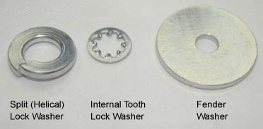
- Split lock washer: These have two features that supposedly prevent loosening: a spring action and an edge that digs into the screw on reversal. According to this thread it seems that everyone from NASA to British Ministry of Defence to the US navy thinks split lock washers are useless. Some of the rationale include the fact that the spring force of the washer is only around 5% of the force from the stretched bolt, and that the edge cannot dig into anything when it flattens out. Yet, millions of these washers are used every year, so one would think they’re not completely useless.According to the “Handbook of Bolts and Bolted Joints,” by Bickford, p. 243, the lock washer undergoes additional deformation after it flattens with a spring rate more comparable to that of the bolt. This extra springiness is helpful for preventing fatigue failure, but it’s unlikely that it helps prevent loosening.These washers are probably most effective in joints where the recommended tightness cannot be achieved, such as soft metal, plastic or wood joints. In these cases, the washer would likely not be entirely flat and would indeed dig into the screw surfaces.
- Toothed washers: These have small teeth that dig into adjacent screw and joint material. The consensus seems to be that these are more effective than split lock washers, but will (and must) cause damage to adjacent surfaces, which may affect repeated installation.
- Belleville washers: These are cone shaped (not shown) washers are used more as a precision spring than a locking device. They can be stacked to increase their combined spring rate. Their spring rates are substantially higher than split lock washers. They may provide some protection in high vibration or temperature changes. Wavy washers have a similar purpose.
- Sems: These are screws with freely spinning captured washers–washers that are permanently attached.
- Fender washers: These have a much wider outer diameter than typical washers and are useful on softer materials.
- Loctite: This is actually the preferred method for securing screws against vibration. Loctite is like a glue that hardens when oxygen is removed. The most common type can be removed by heating the joint.
- Castle Nuts: These have slots that accept a cotter pin that goes through a drilled hole in the bolt.
- Lock Wires: Bolts heads with holes are strung together with wire so that they cannot turn relative to each other. Used for vibration resistance and as an anti-tampering device.
- Lock Nuts: The most common type is a nut with a nylon insert. These are very effective (certainly more so than lock-washers), but may not work for reassembly. There are also nuts called “prevailing-torque” locknuts. These have warped threads or tapered features that apply increased friction on the bolt.
Material Selection
There’s a vast amount of different materials, plating’s and coatings to choose from. This talks about many of these options, we’ll focus on some of the more common ones here. The material selection is influenced by required strength, temperature, resistance to corrosion, joint materials, and cost.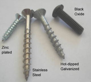
- Zinc plating: Because of steel’s tendency to rust, you’ll never get bare steel fasteners. The most common covering is zinc, but this won’t stand up to outdoor conditions.
- Black Oxide: Most common on socket head cap screws and other machines screws. This provides very mild protection against corrosion and usually has an oil film added for additional protection.
- Hot-Dipped Galvanized: For outdoor use, this provides the best (common) protection next to stainless steel.
- Stainless Steel and aluminium: These materials are inherently resistant to corrosion because they form a tough oxide layer when exposed to oxygen. Note that the strength of stainless is much less than alloy steel, and even less so for aluminium.
- Galvanic Corrosion: When placed in contact along with an electrolite (like humid air), certain metals form little batteries that corrode each other. It happens when the metals are substantially electrochemically different from each other. For instance, brass and zinc plating wouldn’t be a good choice.