Basic terms of a welded joints are shown below Fig 1.
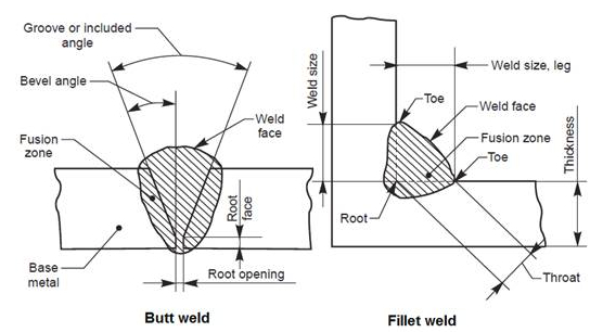
Fig 1.
The five basic types of joints are shown in Fig 2.
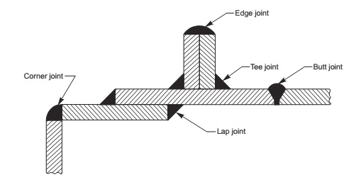
Fig 2.
Position of Weld Symbols on Drawing
The complete method of representation of the welds on the drawing comprises, in addition to the symbol (3), the following Fig 3.
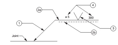
Fig 3.
(i) An arrow line (1) per joint,
(ii) A dual reference line, consisting of two parallel lines; one continuous and one dashed (2a, 2b) and
(iii) A certain number of dimensions (4) and conventional signs (3).
NOTE The dashed line may be drawn either above or below the continuous line. For symmetrical welds, the dashed line is omitted.
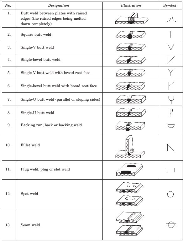
Elementary Welding Symbols
Supplementary Welding Symbols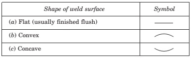
Combination of Elementary and Supplementary Symbols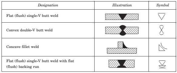
Combination of Elementary and Supplementary Symbols (contd.)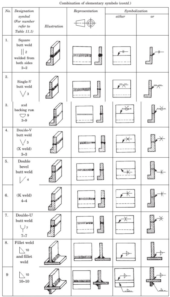
Conventional Signs
The two conventional signs used for welding as per BIS are a circle at the elbow (1), connecting the arrow and the reference line to indicate welding all around and, by a filled-in circle (2) at the elbow to indicate welding on site, as shown in Fig4. These are shown, in addition to the weld symbols of the joint to be made.
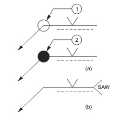
Fig4.
Another convention as per “ISO” International Standards Organisation, indicates the process of welding. For this, the abbreviation of the welding process is written as a note at the tail end of the arrow, forming a 90°V as shown in Fig4. Here, SAW stands for submerged arc welding.
Location of Welds
The location of the welds is specified by the following:
(i) Position of the arrow line,
(ii) Position of the reference line and
(iii) Position of the symbol.
Position of Arrow Line
The arrow joins one end of the continuous reference line, such that it forms an angle with it and is completed by an arrow head. Fig 5 shows the relation between the arrow line and the joint. The terms ‘arrow side’ and ‘other side’ (in case of fillet welding) are used with respect to the continuous plate
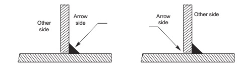
Fig 5.
Fig 6 shows the position of the arrow line with respect to the weld is generally of no special significance .
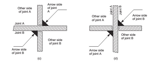
Fig 6.
Indication of Edge Preparation
However, in the case of edge preparation, the arrow line points towards the plate which is prepared Fig 7.
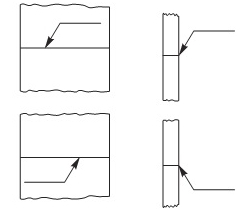
Fig 7.
Position of the Reference Line
The reference line shall preferably be drawn parallel to bottom edge of the drawing and if it is not possible; then it is drawn perpendicular Fig 8.
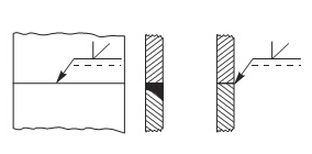
Fig 8.
Position of Symbol
The symbol is placed either above or beneath the reference line as per the following regulation: It is placed on the continuous side of the reference line, if the weld (weld face) is on the arrow side of the joint or on the dashed line side, if the weld is on the other side of the joint Fig 9.
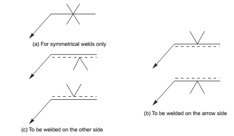
Fig 9.
Dimensioning of Welds
Each weld symbol may be accompanied by a certain number of dimensions. These dimensions are written as indicated in Fig 11.9. It shows (i) the main dimensions relative to the cross-section, written on the left hand side of (before) the symbol and (ii) longitudinal dimension written on the right hand side of (after) the symbol. NOTE The absence of any indication following the symbol, signifies that the weld is to be continuous over the whole length of the workpiece.
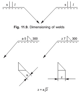
Fig 10.
There are two methods to indicate the dimensions of fillet welds as shown in Fig 10. The letter a(throat thickness), or z(leg length) is always placed in front of the value of the corresponding dimension.
See the video below.